|
| |
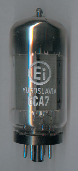
6CA7 is A.F. Output Pentode suitable for use in power amplification
|
|
|
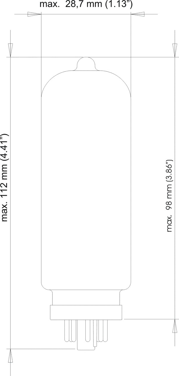
Note that 6CA7 is essentially the same as EL34, except for the physical
dimensions (i.e. diameter) as sketched below. Therefore, for downloading
data sheet, please refer to EL34 page.
|
Quick reference data
-
Anode current Ia=100mA
-
Transcoductance S=12,5mA/V
-
Amplification mg2g1=11
-
Output power, Class B WO=100W
Heating
Heating is indirect by AC or DC, with parallel supply.
| Heater voltage |
Vf |
6,3 |
(V) |
| Heater current |
If |
1,5 |
(A) |
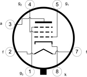
Dimensions and connections
Base: Octal
Operating characteristics
| Supply voltage |
Vb |
265 |
265 |
(V) |
| Anode voltage |
Va |
250 |
250 |
(V) |
| Grid No. 2 series resistor |
Rg2 |
2 |
0 |
(kW) |
| Grid No. 3 voltage |
Vg3 |
0 |
0 |
(V) |
| Grid No 1 . voltage |
Vg1 |
-14,5 |
-13,5 |
(V) |
| Anode current |
la |
70 |
100 |
(mA) |
| Grid No. 2 current |
Ig2 |
10 |
14,9 |
(mA) |
| Transconductance |
S |
11 |
12,5 |
(mA/V) |
| Amplification factor |
mg2g1 |
11 |
11 |
|
| Internal resistance |
Ri |
20 |
17 |
(kW) |
| Load resistance |
Raa |
3 |
2 |
(kW) |
| Grid No. 1 driving voltage |
Vi |
9,3 |
8,7 |
(VRMS) |
| Output Power |
WO |
8 |
11 |
(W) |
| Distortion |
dtot |
10 |
10 |
(%) |
| Grid No. 1 driving voltage for WO = 50 mW |
Vi |
0.65 |
0,5 |
(VRMS) |
- Class B, two tubes in push-pull
Common grid No.2 series resistor
(non decoupled) |
Rg2 |
1000 |
470 |
(W) |
| Grid No.1 voltage |
Vg1 |
-38 |
-32 |
(V) |
| Grid No. 3 voltage |
Vg3 |
0 |
0 |
(V) |
| Grid No. 1 driving voltage |
Vi |
0 |
27 |
27 |
0 |
22,7 |
22,7 |
(VRMS) |
| Load resistance |
Raa |
|
3,4 |
4 |
|
2,8 |
3,8 |
(kW) |
| Stupply voltage |
Vb |
425 |
425 |
400 |
375 |
375 |
350 |
(V) |
| Anode voltage |
Va |
420 |
400 |
375 |
370 |
350 |
325 |
(V) |
| Anode current |
la |
2×30 |
2×120 |
2×100 |
2×35 |
2×120 |
2×93 |
(mA) |
| Grid No. 2 current |
Ig2 |
2×4,4 |
2×25 |
2×25 |
2×4.7 |
2×25 |
2×25 |
(mA) |
| Output power |
WO |
0 |
55 |
45 |
0 |
44 |
36 |
(W) |
| Distortion |
dtot |
|
5 |
6 |
|
5 |
6 |
(%) |
Common grid No.2 series resistor
(non decoupled) |
Rg2 |
750 |
750 |
(W) |
| Grid No.1 voltage |
Vg1 |
-36 |
-39 |
(V) |
| Grid No. 3 voltage |
Vg3 |
0 |
0 |
(V) |
| Grid No. 1 driving voltage |
Vi |
0 |
25,8 |
25,8 |
0 |
23,4 |
23,4 |
(VRMS) |
| Load resistance |
Raa |
|
4 |
5 |
|
11 |
11 |
(kW) |
| Stupply voltage |
Vb |
500 |
500 |
475 |
800 |
800 |
750 |
(V) |
| Anode voltage |
Va |
495 |
475 |
450 |
795 |
775 |
725 |
(V) |
| Anode current |
la |
2×30 |
2×125 |
2×10² |
2×25 |
2×91 |
2×84 |
(mA) |
| Grid No. 2 current |
Ig2 |
2×4 |
2×25 |
2×25 |
2×3 |
2×19 |
2×19 |
(mA) |
| Output power |
WO |
0 |
75 |
58 |
0 |
100 |
90 |
(W) |
| Distortion |
dtot |
|
5 |
6 |
|
5 |
6 |
(%) |
- Class AB, two tubes in push-pull
| Load resistance |
Raa |
3,4 |
(kW) |
Common grid No.2 series resistor
(non decoupled) |
Rg2 |
470 |
(W) |
| Common cathode resistor |
Rk |
130 |
(W) |
| Grid No. 3 voltage |
Vg3 |
0 |
(V) |
| Grid No. 1 driving voltage |
Vi |
0 |
21 |
(V) |
| Stupply voltage |
Vb |
375 |
375 |
(V) |
| Anode to earth voltage |
Va+VRk |
355 |
350 |
(V) |
| Anode current |
la |
2×75 |
2×95 |
(mA) |
| Grid No. 2 current |
Ig2 |
2×11.5 |
2×22.5 |
(mA) |
| Output power |
WO |
0 |
35 |
(W) |
| Distortion |
dtot |
|
5 |
(%) |
Limiting - maximal values (design center rating system)
| Anode voltage |
Vao |
2000 |
(V) |
| Va |
800 |
| Grid No. 2 voltage |
Vg2o |
800 |
(V) |
| Vg2 |
500 |
| Anode dissipation |
Wa(Vi=0) |
25 |
(W) |
| Wa(Vi>0) |
27,5 |
| Grid No. 2 dissipation |
Wg2 |
8 |
(W) |
| Cathode current |
Ik |
150 |
(mA) |
| Grid No. 1 resistor |
Rg1(Class A & AB) |
0,7 |
(MW) |
| Rg1(Class B) |
0,5 |
| Cathode to heater voltage |
Vkf |
100 |
(V) |
|