|
| |
Quick reference data
Heating
Indirect by AC or DC; parallel supply.
| Heater voltage |
Vf |
6,3 |
(V) |
| Heater current |
If |
760 |
(mA) |
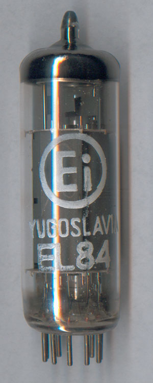
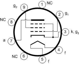
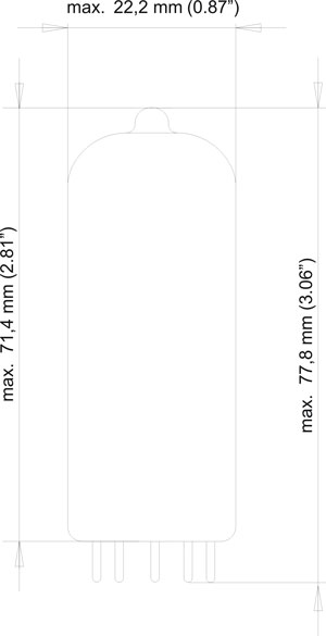
Dimensions and connections
Base: Noval
| Anode voltage |
Va |
250 |
(V) |
| Grid No. 2 voltage |
Vg2 |
250 |
(V) |
| Grid No. 1 voltage |
Vg1 |
-7,3 |
(V) |
| Cathode resistor |
Rk |
135 |
(W) |
| Load resistance |
Ra |
5,2 |
(kW) |
| Grid No. 1 driving voltage |
Vi |
0 |
0,3 |
3,4 |
4,3 |
4,7 |
(VRMS) |
| Anode current |
Ia |
48 |
|
|
49,5 |
49,2 |
(mA) |
| Grid No. 2 current |
Ig2 |
5,5 |
|
|
10,8 |
11,6 |
(mA) |
| Transconductance |
S |
11,3 |
|
|
|
|
(mA/V) |
| Amplification |
mg2g1 |
19 |
|
|
|
|
|
| Internal resistance |
Ri |
38 |
|
|
|
|
(kW) |
| Output power |
Wo |
0 |
0,05 |
4,5 |
5,7 |
6 |
(W) |
| Distortion |
total |
dtot |
|
|
6,8 |
10 |
|
(%) |
| second harmonic |
d2 |
|
|
3 |
2 |
|
(%) |
| third harmonic |
d3 |
|
|
5,8 |
9,5 |
|
(%) |
| Anode voltage |
Va |
250 |
(V) |
| Grid No. 2 voltage |
Vg2 |
250 |
(V) |
| Grid No. 1 voltage |
Vg1 |
-7,3 |
(V) |
| Cathode resistor |
Rk |
135 |
(W) |
| Load resistance |
Ra |
4,5 |
(kW) |
| Grid No. 1 driving voltage |
Vi |
0 |
0,3 |
3,5 |
4,4 |
4,8 |
(VRMS) |
| Anode current |
Ia |
48 |
|
|
50,6 |
50,5 |
(mA) |
| Grid No. 2 current |
Ig2 |
5,5 |
|
|
10 |
11 |
(mA) |
| Transconductance |
S |
11,3 |
|
|
|
|
(mA/V) |
| Amplification |
mg2g1 |
19 |
|
|
|
|
|
| Internal resistance |
Ri |
38 |
|
|
|
|
(kW) |
| Output power |
Wo |
0 |
0,05 |
4,5 |
5,7 |
6 |
(W) |
| Distortion |
total |
dtot |
|
|
7,5 |
10 |
|
(%) |
| second harmonic |
d2 |
|
|
5,7 |
5 |
|
(%) |
| third harmonic |
d3 |
|
|
4,5 |
8 |
|
(%) |
| Anode voltage |
Va |
250 |
(V) |
| Grid No. 2 voltage |
Vg2 |
250 |
(V) |
| Grid No. 1 voltage |
Vg1 |
-8,4 |
(V) |
| Cathode resistor |
Rk |
210 |
(W) |
| Load resistance |
Ra |
7 |
(kW) |
| Grid No. 1 driving voltage |
Vi |
0 |
0,3 |
3,5 |
5,5 |
(VRMS) |
| Anode current |
Ia |
36 |
|
36,8 |
36 |
(mA) |
| Grid No. 2 current |
Ig2 |
4,1 |
|
8,5 |
14,6 |
(mA) |
| Transconductance |
S |
10 |
|
|
|
(mA/V) |
| Amplification |
mg2g1 |
19 |
|
|
|
|
| Internal resistance |
Ri |
40 |
|
|
|
(kW) |
| Output power |
Wo |
0 |
0,05 |
4,2 |
5,6 |
(W) |
| Distortion |
total |
dtot |
|
|
10 |
|
(%) |
| second harmonic |
d2 |
|
|
1,7 |
|
(%) |
| third harmonic |
d3 |
|
|
8,7 |
|
(%) |
| Anode voltage |
Va |
250 |
(V) |
| Grid No. 2 voltage |
Vg2 |
210 |
(V) |
| Grid No. 1 voltage |
Vg1 |
-6,4 |
(V) |
| Cathode resistor |
Rk |
160 |
(W) |
| Load resistance |
Ra |
7 |
(kW) |
| Grid No. 1 driving voltage |
Vi |
0 |
0,3 |
3,4 |
3,8 |
(VRMS) |
| Anode current |
Ia |
36 |
|
36,6 |
36,5 |
(mA) |
| Grid No. 2 current |
Ig2 |
3,9 |
|
7,3 |
8 |
(mA) |
| Transconductance |
S |
10,4 |
|
|
|
(mA/V) |
| Amplification |
mg2g1 |
19 |
|
|
|
|
| Internal resistance |
Ri |
40 |
|
|
|
(kW) |
| Output power |
Wo |
0 |
0,05 |
4,3 |
4,7 |
(W) |
| Distortion |
total |
dtot |
|
|
10 |
|
(%) |
| second harmonic |
d2 |
|
|
1,8 |
|
(%) |
| third harmonic |
d3 |
|
|
9,3 |
|
(%) |
Notes:
- Grid No. 2 driving voltage measured with fixed bias
- Distortion at Ig1=+0,3mA
- Class B, two tubes in push-pull
| Anode voltage |
Va |
250 |
300 |
(V) |
| Grid No. 2 voltage |
Vg2 |
210 |
300 |
(V) |
| Grid No. 1 voltage |
Vg1 |
-11,6 |
-14,7 |
(V) |
| Load resistance |
Raa |
8 |
8 |
(kW) |
| Grid No. 1 driving voltage |
Vi |
0 |
8 |
0 |
10 |
(VRMS) |
| Anode current |
Ia |
2×10 |
2×37,5 |
2×7,5 |
2×46 |
(mA) |
| Grid No. 2 current |
Ig2 |
2×1,1 |
2×7,5 |
2×0,8 |
2×11 |
(mA) |
| Output power |
Wo |
0 |
11 |
0 |
17 |
(W) |
| Distortion |
dtot |
|
3 |
|
4 |
(%) |
- Class AB, two tubes in push-pull
| Anode voltage |
Va |
250 |
300 |
(V) |
| Grid No. 2 voltage |
Vg2 |
210 |
300 |
(V) |
| Common cathode resistor |
Rk |
130 |
130 |
(W) |
| Load resistance |
Raa |
8 |
8 |
(kW) |
| Grid No. 1 driving voltage |
Vi |
0 |
8 |
0 |
10 |
(VRMS) |
| Anode current |
Ia |
2×31 |
2×37,5 |
2×36 |
2×46 |
(mA) |
| Grid No. 2 current |
Ig2 |
2×3,5 |
2×7,5 |
2×4 |
2×11 |
(mA) |
| Output power |
Wo |
0 |
11 |
0 |
17 |
(W) |
| Distortion |
dtot |
|
3 |
|
4 |
(%) |
| Anode voltage |
Va |
250 |
(V) |
| Cathode resistor |
Rk |
270 |
(W) |
| Load resistance |
Ra |
3,5 |
(kW) |
| Grid No. 1 driving voltage |
Vi |
0 |
1 |
6,7 |
(VRMS) |
| Anode current |
Ia |
34 |
|
36 |
(mA) |
| Output power |
Wo |
|
0,05 |
1,95 |
(W) |
| Distortion |
dtot |
|
|
9 |
(%) |
- Class AB, two tubes in push-pull
| Anode voltage |
Va |
250 |
300 |
(V) |
| Common cathode resistor |
Rk |
270 |
270 |
(W) |
| Load resistance |
Raa |
10 |
10 |
(kW) |
| Grid No. 1 driving voltage |
Vi |
0 |
8,3 |
0 |
10 |
(VRMS) |
| Anode current |
Ia |
2×20 |
2×21,7 |
2×24 |
2×26 |
(mA) |
| Output power |
Wo |
0 |
3,4 |
0 |
5,2 |
(W) |
| Distortion |
dtot |
|
2,5 |
|
2,5 |
(%) |
| Grid No. 1 driving voltage for Wo=50mW |
Vi |
|
0,95 |
|
0,9 |
(VRMS) |
| Anode voltage |
Vao |
550 |
(V) |
| Va |
300* |
| Anode dissipation |
Wa |
12* |
(W) |
| Grid No. 2 voltage |
Vg2o |
550 |
(V) |
| Vg2 |
300* |
| Grid No. 2 dissipation |
Wg2 |
2 |
(W) |
| Wg2p |
4 |
| Grid No. 1 voltage |
Vg1 |
-100 |
(V) |
| Cathode current |
Ik |
65 |
(mA) |
| Grid No. 1 resistor |
automatic bias |
Rg1 |
1 |
(MW) |
| fixed bias |
0,3 |
| Cathode to heater voltage |
Vkf |
100 |
(V) |
*When the heater and positive voltages are obtained from a storage battery by
means of vibrator, the max. values of Va and Vg2 are 250V
and that of Wa is 9W.
|